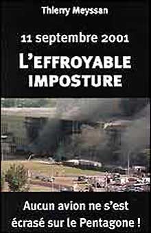
Тьерри Мейссан - 11 сентября 2001
Здесь можно скачать бесплатно "Тьерри Мейссан - 11 сентября 2001" в формате fb2, epub, txt, doc, pdf. Жанр: Публицистика, издательство Карно, год 2002. Так же Вы можете читать книгу онлайн без регистрации и SMS на сайте LibFox.Ru (ЛибФокс) или прочесть описание и ознакомиться с отзывами.
Название:
11 сентября 2001
Автор:
Издательство:
Карно
Жанр:
Год:
2002
ISBN:
нет данных
Скачать:


Скачивание начинается... Если скачивание не началось автоматически, пожалуйста нажмите на эту ссылку.
Вы автор?
Жалоба
Жалоба
Все книги на сайте размещаются его пользователями. Приносим свои глубочайшие извинения, если Ваша книга была опубликована без Вашего на то согласия.
Напишите нам, и мы в срочном порядке примем меры.
Напишите нам, и мы в срочном порядке примем меры.
Как получить книгу?
Оплатили, но не знаете что делать дальше? Инструкция.
Описание книги "11 сентября 2001"
Описание и краткое содержание "11 сентября 2001" читать бесплатно онлайн.
Эта книга произвела фурор и мгновенно стала бестселлером во Франции, а затем и в других европейских странах. В США власти более года препятствовали выходу в свет этой книги, но она все же была опубликована – и сразу стала мощнейшим подспорьем для антивоенного и «антиглобалистского» движения. То, что книга Мейссана не только не стала бестселлером у нас в стране, а, напротив, была фактически замолчана, – явление позорное, говорящее о продажном, марионеточном, характере политической науки в России.
At the exterior wall, truss top chords were supported in bearing off seats extending from the spandrels at alternate columns. Welded plate connections with an estimated ultimate capacity of 90 kips (refer to Appendix B) tied the pairs of trusses to the exterior wall for out-of-plane forces. At the central core, trusses were supported on seats off a girder that ran continuously past and was supported by the core columns. Nominal out-of-plane connection was provided between the trusses and these girders.
Figure 2-7 Shows the erection of prefabricated components, forming exterior wall and floor deck units.
This is a view from the North Tower, looking north toward the Empire State Building. Note the yellow and red lines in the concrete. What are these? Note, in particular, the three V-shaped features in/on the concrete, along the north wall (but not along the west wall).
Figure 2-8 Shows the erection of floor framing during original construction.
This is another view from the North Tower (looking north west). The other high-rise is the Verizon building. Note the vertical gaps in the box columns of the perimeter wall. Gaps in the box columns do not seem to be a sensible feature in a supposedly load bearing wall. Is this because the perimeter wall was not required to carry much of the weight of the building, but was mainly a feature designed to give the WTC its required rigidity (against wind loading)? Notice the three parallel light-colored lines (about 4 inches wide) in the concrete. One also wonders why the pile of steel in the foreground was hoisted up the building, unless it was to be incorporated in the structure.
These figures illustrate this construction, and Figure 2-9 shows a cross-section through typical floor framing. Floors were designed for a uniform live load of 100 pounds per square foot (psf) over any 200-square-foor area with allowable live load reductions taken over larger areas. At building corners, this amounted to a uniform live load (unreduced) of 55 psf.
At approximately 10,000 locations in each building, viscoelastic dampers extended between the lower chords of the joists and gusset plates mounted on the exterior columns beneath the stiffened seats (Detail A in Figure 2-6). I find it really strange that dampers are attached to only one end of each truss. It doesn't make much sense to dampen vibration at one end while letting the other end «blow in the breeze». These dampers were the first application of this technology in a high-rise building, and were provided to reduce occupant perception of wind-induced building motion.
Figure 2-2 Representative structural framing plan, upper floors.
You may wish to compare the above floor plan with this one taken from Godfrey, GB (Editor); Multi-Storey Buildings in Steel, Second Edition; Collins, London, England,1985, ISBN 0 00 383031 4. The differences are quite telling.
Figure 2-2-A Structural system for typical floor.
The numbers in the figure denote:
13 – Perimeter frame
14 – Bar joists 900 mm deep
15 – Secondary joists
16 – Horizontal floor bracing
17 – Core box columns
That the second floor plan is more accurate than the first, is plain from the above photo where the diagonal brace members (the V-shaped features in the diagrams) are clearly visible in the concrete along the north wall, but not along the west wall (as in the second diagram but not the first).
Pairs of flat bars extended diagonally from the exterior wall to the top chord of adjacent trusses (this is puzzling, as the top chords of the trusses are set in the concrete slab, yet one can clearly see these bars on the concrete surface in the above mentioned photo). These diagonal flat bars, which were typically provided with shear studs, provided horizontal shear transfer between the floor slab and exterior wall, as well as out-of-plane bracing for perimeter columns not directly supporting floor trusses (Figure 2-2).
The core consisted of 5-inch concrete fill on metal deck supported by floor framing of rolled structural shapes, in turn supported by a combination of wide flange shape and box-section columns. Some of these columns were very large, with cross-sections measuring 14 inches wide by 36 inches deep. In upper stories, these rectangular box columns transitioned into heavy rolled wide flange shapes (see Appendix B for a picture of the transition from box column to H-column).
Between the 106th and 110th floors, a series of diagonal braces were placed into the building frame. These diagonal braces together with the building columns and floor framing formed a deep outrigger truss system that extended between the exterior walls and across the building core framing. A total of 10 outrigger truss lines were present in each building
Figure 2-10 Outriger truss system at tower roof.
(Figure 2-10), 6 extending across the long direction of the core and 4 extending across the short direction of the core. This outrigger truss system provided stiffening of the frame for wind resistance, mobilized some of the dead weight supported by the core to provide stability against wind-induced overturning, and also provided direct support for the transmission tower on WTC 1. Although WTC 2 did not have a transmission tower, the outrigger trusses in that building were also designed to support such a tower.
Figure 2-11. Location of subterranean structure.
A deep subterranean structure was present beneath the WTC Plaza (Figure 2-11) and the two towers. The western half of this substructure, bounded by West Street to the west and by the 1/9 subway line that extends approximately between West Broadway and Greenwich Street on the east, was 70 feet deep and contained six subterranean levels. The structure housed a shopping mall and building mechanical and electrical services, and it also provided a station for the PATH subway line and parking for the complex.
Above, is a photo of the area shaded in blue, in Figure 2-11 (looking north). In the foreground, are the foundations for the central core of the South Tower. The North Tower can be seen on the left further back. Two subway lines can be seen crossing the site (the two bridge-like structures). The site extended from West Street in the west to the old extention of Greenwich Street in the east (which was ripped up to make way for WTCs 4 and 5) and from Vesey Street in the north to Liberty Street in the south.
Prior to construction, the site was underlain by deep deposits of fill material, informally placed over a period of several hundred years to displace the adjacent Hudson River shoreline and create additional usable land area. In order to construct this structure, the eventual perimeter walls for the subterranean structure were constructed using the slurry wall technique. After the concrete wall was cured and attained sufficient strength, excavation of the basement was initiated. As excavation proceeded downward, tieback anchors were drilled diagonally down through the wall and grouted into position in the rock deep behind the walls. These anchors stabilized the wall against the soil and water pressures from the unexcavated side as the excavation continued on the inside. After the excavation was extended to the desired grade, foundations were formed and poured against the exposed bedrock, and the various subgrade levels of the structure were constructed.
Floors within the substructure were of reinforced concrete flat-slab construction, supported by structural steel columns. Many of these steel columns also provided support for the structures located above the plaza level. After the floor slabs were constructed, they were used to provide lateral support for the perimeter walls, holding back the earth pressure from the unexcavated side. The tiebacks, which had been installed as a temporary stabilizing measure, were decommissioned by cutting off their end anchorage hardware and repairing the pockets in the slurry wall where these anchors had existed.
Tower foundations beneath the substructure consisted of massive spread footings, socketed into and bearing directly on the massive bedrock. Steel grillages, consisting of layers of orthogonally placed steel beams, were used to transfer the immense column loads, in bearing, to the reinforced concrete footings.
2.1.3 Fire Protection
The fire safety of a building is provided by a system of interdependent fire protection features, including suppression systems, detection systems, notification devices, smoke management systems, and passive systems such as compartmentation and structural protection. The failure of any of these fire protection systems will impact the effectiveness of the other systems in the building.
2.1.3.1 Passive Protection
In WTC 1, structural elements up to the 39th floor were originally protected from fire with a spray applied product containing asbestos (Nicholson, et al. 1980). These asbestos-containing materials were later abated inside the building, either through encapsulation or replacement. On all other floors and throughout WTC 2, a spray-applied, asbestos-free mineral fiber material was used. Each element of the steel floor trusses was protected with spray-applied material. The specific material used was a low-density, factory-mixed product consisting of manufactured inorganic fibers, proprietary cement-type binders, and other additives in low concentrations to promote wetting, set, and dust control. Air setting, hydraulic setting, and ceramic setting binders were added in varying quantities and combinations or singly at the site, depending on the particular application and weather conditions. Finally, water was added at the nozzle of the spray gun as the material was sprayed onto the member to be protected. The average thickness of spray-applied fire proofing on the trusses was 3/4 inch. In the mid-1990s, a decision was made to upgrade the fire protection by applying additional material onto the trusses so as to increase fire proofing thickness to 1-1/2 inches (somehow, I doubt that 3 inches (1-1/2 inches «either side») of fire proofing would stick to the 1.09 inch diagonal rod of the trusses). The fire proofing upgrade was applied to individual floors as they became vacant. By September 11, 2001, a total of 31 stories had been upgraded, including the entire impact zone in WTC 1 (floors 94-98), but only the 78th floor in the impact zone in WTC 2 (floors 78-84).
Spandrels and girders were specified to have sufficient protection to achieve a 3-hour rating. Except for the interior face of perimeter columns between spandrels, which were protected with a plaster material, spray applied materials similar to those used on the floor systems were used. The thickness of protection on spandrels and girders varied, with the more massive steel column sections receiving reduced fire proofing thickness relative to the thinner elements.
The primary vertical compartmentation was provided by the floor slabs that were cast flush against the spandrel beams at the exterior wall, providing separation between floors at the building perimeter. After a fire in 1975 (note that this fire did not cause the building to collapse) vertical penetrations for cabling and plumbing were sealed with fire-resistant material. At stair and elevator shafts, separation was provided by a wall system constructed of metal studs and two layers of 5/8– inch thick gypsum board on the exterior and one layer of 5/8-inch thick gypsum board on the interior. These assemblies provided a 2-hour rating. Horizontal compartmentation varied throughout the complex. Some separating walls ran from slab to slab, while others extended only up to the suspended ceiling. A report by the New York Board of Fire Underwriters (NYBFU) titled One World Trade Center Fire, February 13, 1975 (NYBFU 1975) presents a detailed discussion of the compartmentation features of the building at that time.
2.1.3.2 Suppression
When originally constructed, the two towers were not provided with automatic fire sprinkler protection. However, such protection was installed as a retrofit circa 1990, and automatic sprinklers covered nearly 100 percent of WTC 1 and WTC 2 at the time of the September 11 attacks. In addition, each building had standpipes running through each of its three stairways. A 1.5-inch hose line and a cabinet containing two air pressurized water (APW) extinguishers were also present at each floor in each stairway.
The primary water supply was provided by a dedicated fire yard main that looped around most of the complex. This yard main was supplied directly from the municipal water supply. Two remotely located high pressure, multi-stage, 750-gallons per minute (gpm) electrical fire pumps took suction from the New York City municipal water supply and produced the required operating pressures for the yard main.
Each tower had three electrical fire pumps that provided additional pressure for the standpipes. One pump, located on the 7th floor, received the discharge from the yard main fire pumps and moved it up to the 41st floor, where a second 750-gpm fire pump pushed it up to a third pump on the 75th floor. Each fire pump produced sufficient pressure to supply water to the pump two stages up from it in the event that any one pump should fail. Several 5,000-gallon storage tanks, filled from the domestic water system, provided a secondary water supply. Tanks on the 41st, 75th, and 110th floors provided water directly to a standpipe system. A tank on the 20th floor supplied water directly to the yard main. Numerous Fire Department of New York (FDNY) connections were located around the complex to allow the fire department to boost water pressure in the buildings.
2.1.3.3 Smoke Management
A zoned smoke control system was built into each building's ventilation systems and was activated upon direction of the responding FDNY Incident Commander. The system was designed to limit smoke spread from the tenant areas to the core area, thereby assisting both individuals evacuating from an area and those responding to the scene by limiting smoke spread into the core.
2.1.3.4 Fire Department Features
At the time of the 1993 World Trade Center bombing, a centralized Fire Command Center (FCC) for the two towers was present at the Concourse level. This FCC was located in the B-1 level Operations Control Center (OCC). Following the 1993 bombing, additional FCCs were installed in the lobbies of each tower.
A Radiax cable and antenna were installed in the WTC complex to facilitate the use of FDNY radios in the towers. Fire department telephones were provided in both towers on odd floors in Stairway 3, as well as on levels B-1, B-4, and B-6.
На Facebook
В Твиттере
В Instagram
В Одноклассниках
Мы Вконтакте
Подписывайтесь на наши страницы в социальных сетях.
Будьте в курсе последних книжных новинок, комментируйте, обсуждайте. Мы ждём Вас!
Подписывайтесь на наши страницы в социальных сетях.
Будьте в курсе последних книжных новинок, комментируйте, обсуждайте. Мы ждём Вас!
Похожие книги на "11 сентября 2001"
Книги похожие на "11 сентября 2001" читать онлайн или скачать бесплатно полные версии.


Понравилась книга? Оставьте Ваш комментарий, поделитесь впечатлениями или расскажите друзьям
Уважаемый посетитель, Вы зашли на сайт как незарегистрированный пользователь.
Мы рекомендуем Вам зарегистрироваться либо войти на сайт под своим именем.
Мы рекомендуем Вам зарегистрироваться либо войти на сайт под своим именем.
Отзывы о "Тьерри Мейссан - 11 сентября 2001"
Отзывы читателей о книге "11 сентября 2001", комментарии и мнения людей о произведении.